A student designs a simple integrated circuit device that has two inputs, V_{a} and V_{b}, and two outputs, V_{o} and V_{g}. The inputs are effectively connected internally to a single resistor with effectively infinite resistance. The outputs are effectively connected internally to a perfect source of emf \mathcal{E}. The integrated circuit is configured so that \mathcal{E}=G\left(V_{a}-V_{b}\right), where G is a very large number somewhere between 10^{7} and 10^{9}. The circuits below are chosen so that the precise value of G is unimportant. On the left is an internal schematic for the device; on the right is the symbol that is used in circuit diagrams.

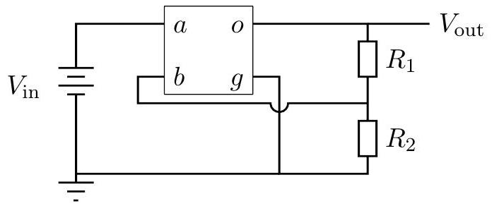
a. Consider the following circuit. R_{1}=8.2 \mathrm{k} \Omega and R_{2}=560 \Omega are two resistors. Terminal g and the negative side of V_{\text {in }} are connected to ground, so both are at a potential of 0 volts. Determine the ratio V_{\text {out }} / V_{\text {in }}.
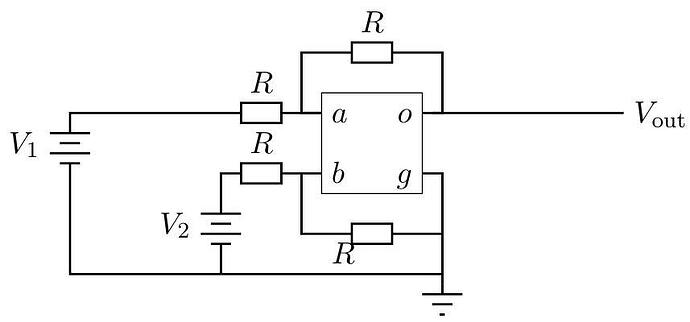
b. Consider the following circuit. All four resistors have identical resistance R. Determine V_{\text {out }} in terms of any or all of V_{1}, V_{2}, and R.
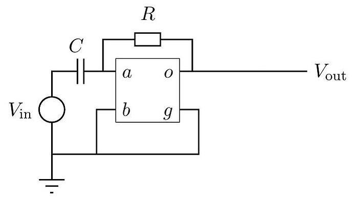
c. Consider the following circuit. The circuit has a capacitor C and a resistor R with time constant R C=\tau. The source on the left provides variable, but bounded voltage. Assume V_{\text {in }} is a function of time. Determine V_{\text {out }} as a function of V_{\mathrm{in}}, and any or all of time t and \tau.


